Gearbox Components and Parts: Everything You Need to Know
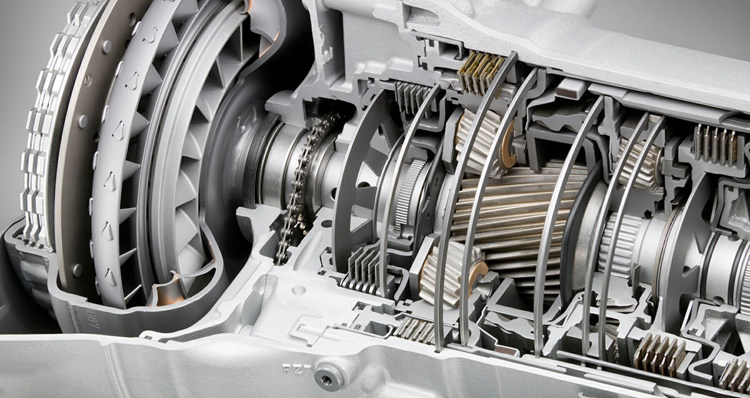
Table of Contents
Main gearbox components and partsClutch shaft
Counter shaft
Main shaft
Gears
Bearings
Gearbox parts diagram
Manual transmission componentsClutch Disc
Clutch Pedal
Synchronizers
Flywheel
Gears
Selector Fork
Stick Shift
Collar
Automatic transmission componentsTorque Converter
Oil Pump
Planetary Gear Set
Clutch Packs
Output Shaft
Brake Band
Oil Pan
Valve Body
Buy Equipment or Ask for a Service
A gearbox is a contained gear train, or a mechanical unit or component consisting of a series of integrated gears within a housing. In the most basic sense, a gearbox functions like any system of gears; it alters torque and speed between a driving device like a motor and a load. To know how a gearbox operates, it is necessary to understand the gearbox components and functions. In this article, we will discuss the gearbox components and parts. Read this new blog in Linquip to find about all components of gearbox and their functions.
⇒ View a List of Gearbox for Sale and Their Suppliers ⇐
 Main gearbox components and parts
Clutch shaft
Counter shaft
Main shaft
Gears
Bearings
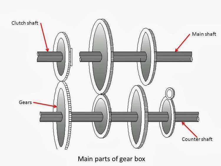
The main gearbox spare parts list is described below.
· Clutch shaft
A Clutch shaft or driving shaft is a shaft that takes power from the engine to further supply to other shafts. As the name suggests, the driving shaft is connected via a clutch and when the clutch is engaged, the driving shaft also rotates. The clutch shaft has only one gear fixed on it and it rotates at the same speed as the engine crankshaft.
Find All Clutch Shaft in Linquip
· Counter shaft
A counter shaft is a shaft that connects with the clutch shaft directly. It contains the gear which connects it to the clutch shaft as well as the main shaft. It may be run at the engine speed or at lower than engine speed according to gear ratio.
 · Main shaft
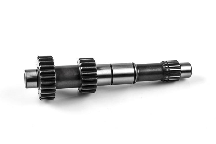
It is the shaft that runs at the vehicle’s speed. It carries power from the counter shaft by use of gears and according to the gear ratio, it runs at different speeds and torque compared to the counter shaft. One end of this shaft is connected with the universal shaft.
· Gears
Gears are used to transmit power from one shaft to another. The amount of torque transmitted via gears depends on the number of teeth and size of the gear. Higher the gear ratio, higher the torque/acceleration, and lesser the speed. All the gears are fixed on their respective shafts except the ones on the main shaft; they can slide into either direction along the shaft.
· Bearings
Whenever the rotary motion encounters, bearings are required to support the revolving part and reduce the friction. In the gearbox, both the counter and main shaft are supported by the bearing.
Find All Bearings in Linquip
 Read More on Linquip
Industrial Gearbox A Comprehensive Review on Features, Types and its Usability
The Ultimate Guide to the Types of Gearbox
Differences Between Worm and Helical Gear
Types of Bevel Gears
The difference between gearbox and transmission
Gearbox parts diagram
In a gearbox, the counter shaft is mashed to the clutch with the use of a couple of gears. So the counter shaft is always in running condition. When the counter shaft is brought in contact with the main shaft by use of meshing gears, the main shaft starts to rotate according to the gear ratio. When the driver wants to change the gear ratio, simply press the clutch pedal which disconnects the counter shaft with the engine and connects the main shaft with the counter shaft by another gear ratio by use of the gearshift lever.
The diagram of the industrial gearbox components is shown in the figure below.
 Manual transmission components
Clutch Disc
Clutch Pedal
Synchronizers
Flywheel
Gears
Selector Fork
Stick Shift
Collar
Here we describe the manual gearbox parts list.
· Clutch Disc
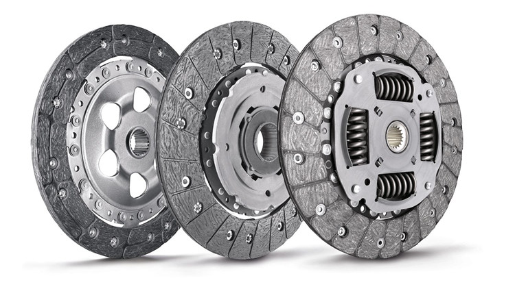
The clutch disc is what assists in transferring the torque from the engine to the manual transmission system. The disc is controlled by the driver stepping on the clutch pedal.
· Clutch Pedal
The clutch pedal is actually a separate gear that is controlled by hydraulics. It allows for the clutch to be disengaged by pressing on the clutch pedal with your foot.
· Synchronizers
The synchronizers stimulate the engagement between the collar and the gear so that their speeds can be synchronized. Sometimes the speeds could end up being different, so you need the synchronizers to prevent that from happening.
· Flywheel
The flywheel is a circular component that sends torque from the engine to the clutch disc.
· Gears
The transmission has gears of all different sizes. There are big gears with lots of teeth and small gears with fewer teeth. Big gears generate extra torque to slow down the speed of the vehicle. Smaller gears generate less torque, which allows the vehicle to travel faster.
· Selector Fork
This is a gear that looks like a mechanical arm. It allows the collars to move on the output shaft.
· Stick Shift
This is the component that you control with your hand. It is the vertical stick that protrudes out of the central console. It is connected to the gearbox for you to switch gears with it.
· Collar
When you select a gear, the collar locks the selection in place and allows the torque to pass to the output shaft.
 Read More on Linquip
Parts of Generator: a Simple, Yet Useful Guide
Steam Turbine Parts: A Comprehensive and understandable Introduction to All Components
Cooling Tower Parts and Functions: A Concise 10,000-Foot yet Essential View
Heat Exchanger Parts: Description of Configuration
Torque Converter
Oil Pump
Planetary Gear Set
Clutch Packs
Output Shaft
Brake Band
Oil Pan
Valve Body
Automatic transmission components
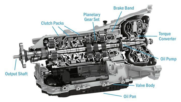
The basic components of an automatic transmission are described below.
· Torque Converter
On automatic transmissions, the torque converter takes the place of the clutch found on standard shift vehicles. It is there to allow the engine to continue running when the vehicle comes to a stop.
The torque converter is a large doughnut-shaped fluid coupling (10″ to 15″ in diameter) that is mounted between the engine and the transmission. It consists of three internal elements that work together to transmit power to the transmission. The three elements of the torque converter are the Pump, the Turbine, and the Stator.
· Oil Pump
The oil pump inside of an automatic transmission works just like any other oil pump. It delivers transmission fluid from the transmission pan to the valve body, which directs all the various components throughout the transmission as needed.
Find All Oil Pump in Linquip
· Planetary Gear Set
Unlike a manual transmission, which has a set of multiple gears that make up the gearbox, an automatic transmission has one or more (usually more) planetary gear sets.
Planetary gears have three sets of gears. The main gear is the sun gear, and it is in the center of the planetary carrier. The second set is the planetary gears. There are typically three or more of these gears and the mesh between the sun gear and the ring gear.
The ring gear surrounds all of the planetary gears with one ring, connecting the entire system and bringing it together. The system works by locking two of the three gear sets at a time. Since each gear set is a different size, this gives you a multitude of gear ratios by merely locking the other gears in place.
· Clutch Packs
With a manual transmission, you manually select the gear you want to engage; an automatic transmission is a little more complicated. Instead of a manual shifter to get your output to the desired ratio, your transmission uses a clutch pack.
A clutch pack has multiple plates compressed together. When the valve body sends oil pressure to the clutch pack, it locks a certain number of clutch packs together, giving you your desired output ratio. Different amounts of oil pressure engage different quantities of discs, which gives your hub a different gear ratio.
· Output Shaft
Once your transmission has completed all of its internal operations, it delivers power to the driveshaft, which in turn supplies power to the hubs. But your transmission’s output shaft is what drives the drive shaft.
On one end, you have a gear that connects to the transmission, and on the other end, you have a splined shaft that connects to the driveshaft via a yoke-type universal joint.
· Brake Band
Brake bands serve one purpose which is to temporarily hold planetary gears. They allow the engine RPM to get in line with the gear ratio before releasing, which allows for smoother shifting. Brake bands work much like drum brakes, with a piston squeezing the band around a drum. The harder the piston pushes, the more braking power is applied.
· Oil Pan
Just like your engine has an oil pan on the bottom, so does your transmission. It does exactly what you think it would; it holds the excess transmission fluid (oil) for the oil pump to pull from when needed. It typically has a transmission fluid filter attached, either internally or externally.
· Valve Body
Your engine has an ECU, and your automatic transmission has a valve body. This component directs all the pressure from the oil pump to all of your transmission components to get the desired results. From the torque converter to the clutch packs, nothing gets transmission fluid without the valve body telling it where to go.
In an automatic transmission, it’s controlled by sensors, which work directly with the transmission control module (TCM) to control where all the fluids are sent. It’s a complicated component, but it’s the most important one in your transmission.
The diagram of automatic transmission components is shown in the figure below.
Find Valve Body in Linquip
 So, now you know everything you need to know about the gearbox components and parts. If you enjoy this article in Linquip, let us know what you think by leaving a reply in the comment section. We will be more than glad to have your viewpoint on different parts of gearbox assembly. Is there any question we can help you through? Feel free to sign up on our website where our experts are prepared to provide you with the most professional advice.
Buy Equipment or Ask for a Service
By using Linquip RFQ Service, you can expect to receive quotations from various suppliers across multiple industries and regions.